Start Job
Job Number *Pilot Name *Select Workflow
Hourly Lone-Worker Check-In
Notes / Issues
Complete Job ends the hourly lone-worker check-ins, records Leaving Site in the audit trail and prepares the leaving-site WhatsApp message.

Complete Job ends the hourly lone-worker check-ins, records Leaving Site in the audit trail and prepares the leaving-site WhatsApp message.
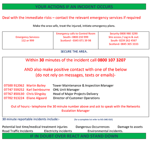
Use the client procedure where applicable. Aerial Drone UK must still be informed within 30 minutes.


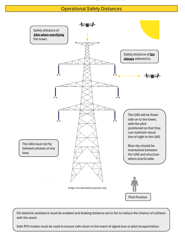
Key reminders: 10 m safety distance when overflying the tower; 5 m safety distance always adhered to; never fly between phases; maintain VLOS and blue sky between the UAS and structure where practicable; obstacle avoidance enabled with 5 m braking distance; safe RTH mode set.

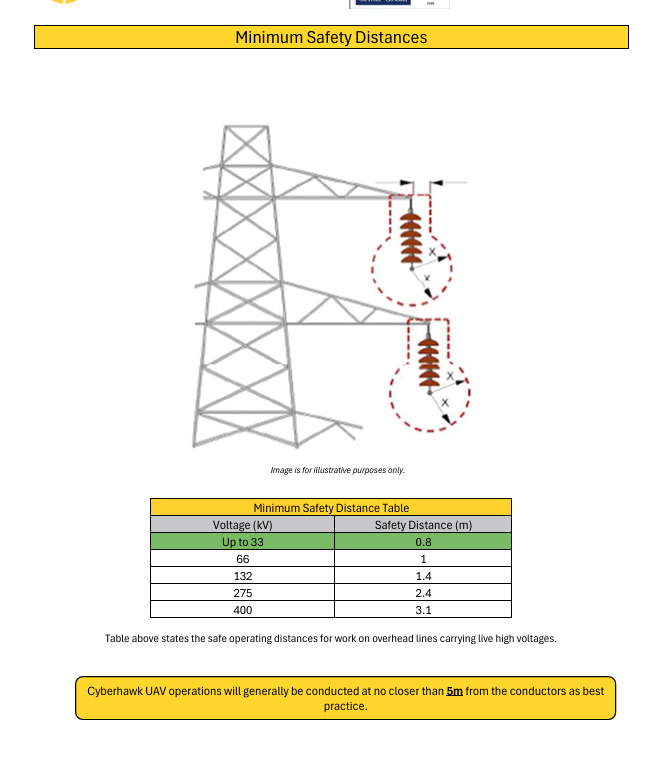
Minimum table: up to 33 kV — 0.8 m; 66 kV — 1.0 m; 132 kV — 1.4 m; 275 kV — 2.4 m; 400 kV — 3.1 m. UAV operations should generally remain no closer than 5 m from conductors as best practice.

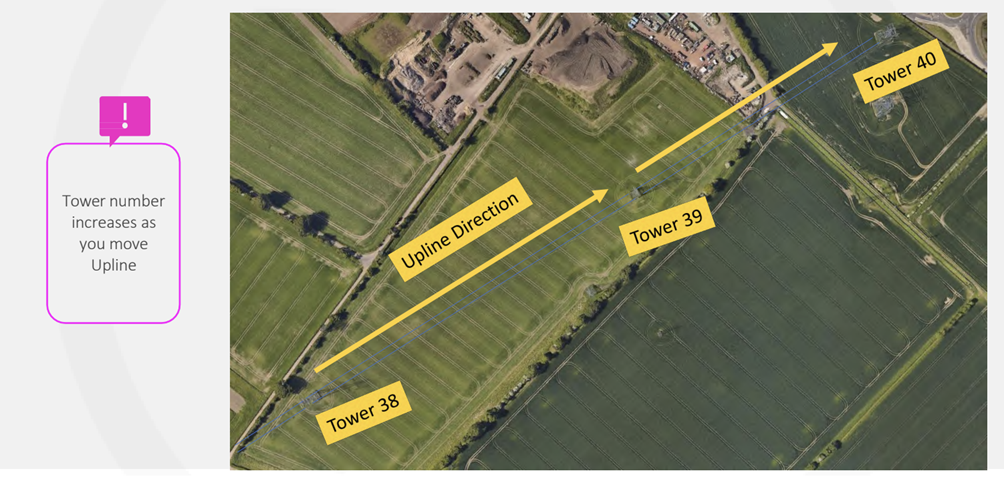
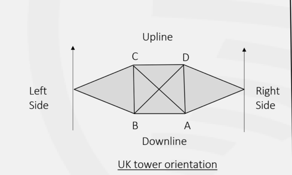
Tower numbers increase as you move Upline. Capture the Upline span so the next structure and wires are visible. Capture the Downline span from Leg C so the next structure and wires are visible.

Overview: capture the whole structure above Leg A. Capture earth wires and connectors; reposition to get everything in frame and take an additional 90° image where required.
Leg A — camera −10° to −15°: make sure the inside of Leg C can be seen. Capture Peak & Upper Crossarm, Upper Insulator, Upper Bracing, Middle Phase Insulator, Middle Crossarm, Middle Bracing, Lower Crossarm, Lower Phase Insulator and Lower Bracing. More than one image may be required to cover bracing to the foundations.
Ground shots — camera −35° to −45°: include signs, ACD, legs, stubs & muffs, Tower ID and Latchways.
Leg D: use −35° to −45° for the lower photo and make sure the inside of Leg B can be seen. Complete ground shots. Then use maximum upward tilt and increase EV to +3 for Lower, Middle and Upper Phase Insulators.
Leg C — camera about −15°: first capture the Downline span, then make sure the inside of Leg A can be seen and repeat the Leg A capture sequence.
Leg B: repeat the Leg D capture sequence.
Use the wide camera for the overall picture, then the zoom camera for detailed photographs. Use a maximum of ×7 optical zoom only. Take plenty of additional detailed photographs where required.
Where GCPs are required, distribute them evenly with good sky view and stable ground. Include coverage around edges/corners and areas of changing terrain. Keep GCPs clear of tall objects and powerlines.
Set the required coordinate system / ellipsoid directly in the Emlid rover before recording. Confirm NTRIP corrections and a FIX solution. Average each GCP for at least 1 minute. Set up the RTK base securely, enter the correct antenna height and average the base position for at least 2 minutes.
Avoid overexposure. Slight underexposure is preferable where needed to protect detail. Confirm motion blur remains suitable for the required GSD.
DJI P1 example — 35 mm lens:
Sensor width ≈ 35.9 mm · Image width = 8192 px.
At 52 m AGL: GSD ≈ 0.65 cm/px.
At 120 m AGL: GSD ≈ 1.50 cm/px.
Confirm RTK FIX before take-off. Monitor RTK status, exposure, focus and aircraft telemetry throughout. If RTK FIX is lost, abort the mapping mission and resolve the issue before continuing.
Use a suitable drone capable of Sphere Panorama capture. Fly at approximately 65 m, capture in JPG, and cover the horizon through to directly beneath the aircraft. Retain the individual full-resolution JPGs and the stitched panorama where one is produced.
Check coverage, sharpness and exposure on site. Save required RTK / PPK data. Where GCPs have been used, export the Emlid GCP Positions spreadsheet / CSV and include it with the job data.
Your hourly lone-worker check-in is due. Please confirm you are OK.